 Bevel Tool 斜面工具Tool Option 工具选项Polygon Extrusion 多边形挤压Shaping 塑形Topology 拓扑学Tool 工具
Shaping
塑形
形状
 Shape modes: 形状模式:Profile 个人资料 with the pictured spline, 有了图片样条,User 使用者 with
the pictured function graph (and disabled 图形功能图(和禁用Symmetry 对称性 option). 选择)
Shape modes: 形状模式:Profile 个人资料 with the pictured spline, 有了图片样条,User 使用者 with
the pictured function graph (and disabled 图形功能图(和禁用Symmetry 对称性 option). 选择)
The flattened or dissolved edges can be given any new shape (e.g., if you bevel a cube’s edge and view it from the side you will see the new shape). Use the Shape setting to define this shape. Note that the following examples were all created in Use Edge mode. The Shape setting can also be used in Use Polygon and Use Point modes on the marked edges:
扁平或溶解的边缘可以赋予任何新的形状(例如,如果你将立方体的边缘削成斜角,从侧面观看,你就会看到新的形状)。使用“形状”设置定义此形状。请注意,以下示例都是在 Use Edge 模式下创建的。形状设置也可以用于使用多边形和使用点模式的标记边缘:

圆形
张力[-∞ . . + ∞% ]
The edge will always be created as a circular segment - if Tension is set to 100%. Otherwise an elliptical shape will be created.
如果张力设置为100% ,边缘将始终被创建为弓形。否则将创建一个椭圆形状。
 Various 各种各样的Tension 紧张
values. 价值观
Various 各种各样的Tension 紧张
values. 价值观
Use this setting to adjust the arc’s tangent (direction AND length). At a value of 100%, the arc will run tangentially from both neighboring surfaces. Lower values will cause the arc to move concavely or convexly, depending on the original edge (outer or inner edge). Note also the Depth setting, which can be used to affect the curvature.
使用此设置来调整反弧的正切线(方向和长度)。当值为100% 时,弧线将从相邻的两个表面切线运行。根据原始边缘(外边缘或内边缘)的不同,较低的值将导致弧线以圆弧或凸弧的方式移动。还要注意深度设置,它可以用来影响曲率。
使用者
用户形状
 Function graphs make it possible to create precise
shapes ( 函数图使创建精确的形状成为可能(Symmetry 对称性 disabled). 禁用)
Function graphs make it possible to create precise
shapes ( 函数图使创建精确的形状成为可能(Symmetry 对称性 disabled). 禁用)
When in this mode, a function graph can be used to shape the original edge. If Symmetry is disabled, the function graph’s shape can be imagined directly between both diverging edges (the Depth setting defines the direction and scale of the curve’s modification). Set Subdivision to a value that will reproduce the curve as accurately as possible.
在这种模式下,可以使用函数图来形成原边。如果禁用对称性,函数图形的形状可以直接在两个发散边之间想象(深度设置定义曲线修改的方向和尺度)。将“细分”设置为一个尽可能精确地再现曲线的值。
Tip: 提示:对称性
If disabled, the function graph will be adapted to to both diverging edges with increasing Offset values. If enabled, the function graph will be duplicated (mirrored at right end).
如果禁用,函数图将适应于偏移量值不断增加的发散边。如果启用,功能图将被复制(镜像在右端)。
等截面
 Beveling the edge shown produces the edges shown:
At left with 斜边显示的边缘产生如下图所示的边缘:Constant Cross Section 等截面 disabled (center) and enabled
(right). 禁用(中)和启用(右)
Beveling the edge shown produces the edges shown:
At left with 斜边显示的边缘产生如下图所示的边缘:Constant Cross Section 等截面 disabled (center) and enabled
(right). 禁用(中)和启用(右)
Depending on the edge to be beveled, a tubular effect (with regard to the rounding volume) can result if the User or Profile modes are used. If Constant Cross Section is enabled, this effect will remain more-or-less constant (especially at corners).
根据要斜切的边缘,如果使用 User 或 Profile 模式,可能会产生管状效果(关于舍入体积)。如果恒定横截面启用,这种效果将保持或多或少不变(特别是在角落)。
个人资料
剖面样条
 2 different splines and the resulting edge
shapes. 2个不同的样条和由此产生的边缘形状
2 different splines and the resulting edge
shapes. 2个不同的样条和由此产生的边缘形状
When in this mode you can freely define the shape of a beveled edge. A spline can be used to define the shape of the edge to be dissolved. The subdivision will be defined by the spline (the Bevel tool’s Subdivision setting will have no effect).
当在这种模式下,你可以自由地定义一个斜边的形状。可以使用样条来定义要溶解的边缘的形状。细分将由样条定义(斜面工具的细分设置将没有任何效果)。
花键的先决条件
Splines used to define an edge’s shape must have the following properties:
用于定义边缘形状的样条函数必须具有以下属性:
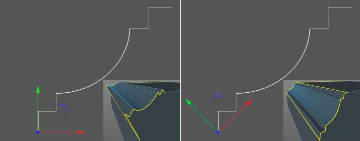
Assuming the Profile Plane is set to XY, the bevel will take place along the geometry’s X axis and will include a variance in the Y direction in order to create the bevel edge shape. In the image above, you can clearly see why the axis orientation at the left, which is created more-or-less automatically when the spline is modeled, fails. The best method is to set the shape axis to the spline’s starting point and rotate it so the spline end point lies on the X axis. This produces decent results because the spline is positioned as an edge between the edges diverged by the Offset setting. The Depth setting must be used to adjust the size of the concave or convex bevel!
假设剖面设置为 XY,斜面将沿着几何体的 x 轴发生,并将包括 y 方向的方差,以创建斜面边缘形状。在上面的图像中,您可以清楚地看到为什么左边的轴方向失败了,当样条被建模时,左边的轴方向或多或少是自动创建的。最好的方法是将形状轴设置为花键的起点,然后将其旋转,使花键的终点位于 x 轴上。这产生了体面的结果,因为样条被定位为边缘之间的边缘偏移设置发散。深度设置必须用来调整凹面或凸面的大小!
Note that problems can occur when beveling 2 or more edges that meet at a given point.
请注意,问题可能发生时,斜面2或更多的边,满足在一个给定的点。
剖面平面
Use this setting to define the plane (object coordinate system!) in which the profile spline lies. This is important for the orientation of the object axis, as described above.
使用此设置定义平面(对象坐标系!)轮廓样条所在的位置。这对于对象轴的方向非常重要,如上所述。