Node Editors
节点编辑器

Don’t be surprised if you land on the same page when calling up the Help for different Node Eidtors. The Editors work almost identically. In the following text we will mention that the one or the other function only works in a specific Node Editor.
不要惊讶,如果你降落在同一个页面时,调用不同的节点 Eidtors 的帮助。编辑们的工作几乎一模一样。在下面的文本中,我们将提到这个或那个函数只能在特定的节点编辑器中工作。
Currently, Cinema 4D has two Node Editors:
目前,Cinema 4D 有两个 Node 编辑器:
- Material Node Editor for creating Node Materials 用于创建节点材质的材质节点编辑器
- Scene Node Editor for creating geometry 用于创建几何图形的场景节点编辑器
常规
 Example: The Material Node Editor (see also 示例: 材质节点编辑器(参见Special informaiton about the Scene Node Editor 关于场景节点编辑器的专门信息).
The following applies to the Material Node Editor:
下面的内容适用于材质节点编辑器:
The Node Editor is where everything takes place when creating and editing Material Nodes (in the following referred to as Nodes). Everything you see in the Node Editor has to be linked with a Node Material (please note this tip), i.e., to create and edit Nodes, a Node Material must be selected. The Node Editor always displays the currently selected Node Material.
节点编辑器是在创建和编辑材质节点(在下面称为节点)时进行所有操作的地方。在 Node Editor 中看到的所有内容都必须链接到一个 Node Material (请注意这个提示) ,也就是说,要创建和编辑 Node,必须选择一个 Node Material。“节点编辑器”始终显示当前选定的节点材质。
Please note that Nodes are quite complex and to use them effectively you need to have a higher level of knowledge about how shading and rendering works in general. However, several functions are very simple when a pre-defined material is used such as the Uber Material, which is almost as easy to use as a normal material (and can still be used in conjunction with an image node in various material channels)._
请注意,节点是相当复杂的,要有效地使用他们,您需要有一个更高水平的知识,如何阴影和渲染工程一般。然而,当使用预先定义的材质时,有几个功能非常简单,例如 Uber Material,它几乎和普通材质一样容易使用(仍然可以与各种材质通道中的图像节点结合使用)。_
The general flow of data is always from left to right. At the far right, everything must always culminate in a Material Node (no Material Node means no working material; only 1 Material Node per material).
一般的数据流总是从左到右。在最右边,一切都必须在材质节点中达到高潮(没有材质节点意味着没有工作材质; 每个材质只有1个材质节点)。
The Node Editor can be opened as follows:
节点编辑器可以如下方式打开:
- Right-clicking on a Node Material and clicking on the 右键单击一个 Node Material,然后单击Node Editor 节点编辑器 button or double-clicking on the Node Material 按钮或双击节点材质
- Clicking on a Node Material’s 点击一个节点材质Node Editor 节点编辑器 button (Basic tab) 按钮(基本标签)
The following applies to the Scene Node Editor:
下面的代码适用于场景节点编辑器:
The Node Edtor’s content is not assigned to a specific element (such as the Material Node Editor to a Node Material) but is itself displayed in the scene. Therefore, the last output Node must always be connected to the scene output via its Op Output output, otherwise no geometry will be generated.
Node Edtor 的内容并没有分配给特定的元素(比如将 Material Node Editor 分配给 Node Material) ,而是自己显示在场景中。因此,最后一个输出节点必须始终通过其 Op Output 输出连接到场景输出,否则不会生成几何图形。
Note that the Scene Node Editor is designed for advanced users and a higher 3D skillset and technical knowledge is needed. See Szenen Nodes Introduction for a brief introduction.
注意,场景节点编辑器是为高级用户设计的,需要更高的3D 技能和技术知识。参见 Szenen 节点简介。
The Scene Node Editor is opened via the Scene Node Editor command in the main menu (Window / Scene Node Editor).
场景节点编辑器通过主菜单(窗口/场景节点编辑器)中的场景节点编辑器命令打开。
The Editor also offers several special functions that are described farther down.
这个编辑器还提供了一些特殊的功能,这些功能将在下面进一步描述。
As with the Node Materials when they were introduced, the Scene Editor comes with a range of additional Nodes for specific uses. Many Nodes (such as the Math Node) work in both the Material Node Editor as in the Scene Node Editor. A description of most Nodes can be found under Individual Assets. The new Scene Nodes can primarily be found in the categories Geometry, Array, Effectors, Fields, Flow Control, Operators and Distribution.
当节点材质被引入时,场景编辑器提供了一系列特定用途的附加节点。许多节点(例如 Math 节点)在两个材质节点编辑器中都工作,就像在场景节点编辑器中一样。大多数节点的描述可以在“个人资产”下找到。新的场景节点主要可以在几何、数组、效果器、字段、流量控制、操作符和分布类别中找到。
RELEASE 23
第23期
Numerous small improvements in the Node View in Cinema 4D R23
4D R23中的 Node View 的许多小改进
Among other things, the following was added in order to improve the readability of the Node setups in the Node Editors:
除此之外,为了提高 Node 编辑器中 Node 设置的可读性,我们添加了以下内容:
- The Node width was reduced and the ports were extended at the Nodes’ outer edge 节点宽度减小,端口扩展到节点的外边缘
- Color coding of the connections analog to the input port color 颜色编码的连接模拟到输入端口的颜色
- Node names and types are now displayed at the top 节点名称和类型现在显示在顶部
- Modifiable level of detail for zooming (Nodes will be displayed simplified when you reduce the size of the Node View) 缩放的可修改细节级别(缩小节点视图大小时将简化节点显示)
- Different Node Views such as hiding unconnected ports can now be used directly at the Node 不同的节点视图,例如隐藏未连接的端口,现在可以直接在节点上使用
Several special Viewport settings for displaying geometry generated by the Scene Node Editor are available in the Project Preferences menu (see Scene Nodes).
在“项目首选项”菜单中可以找到几个特殊的 Viewport 设置,用于显示由“场景节点编辑器”生成的几何图形(参见“场景节点”)。
Note: 注意:Note also the Node Layout (at the top right of the main interface in the 还要注意 Node Layout (在Layouts 布局 drop-down menu), which offers an interface designed for working with Nodes. 下拉菜单) ,它提供了一个用于处理节点的界面
节点编辑器
导航:
As with other Managers; the following hotkeys can be used to navigate in the Node Editor (see also commands in the View menu):
与其他管理器一样,以下热键可用于在节点编辑器中导航(请参阅查看菜单中的命令) :
- Move: Press one of the following keys and drag the mouse: 移动: 按下列键之一并拖动鼠标:
MMB 甲基溴化铵 ,1 + LMB ,Alt + MMB or click and drag in the Navigator. If 或在导航器中单击并拖动。如果Touchscreen 触摸屏 is enabled in the Preferences menu (Input Devices menu), the following will also be enabled: 在首选项菜单(输入设备菜单)中启用,以下也将启用: Mouse wheel up/down (move vertically) and 鼠标滚轮向上/向下(垂直移动)和 - Zoom: Press one of the following buttons
and drag the mouse: 按下下面的按钮之一并拖动鼠标:
Alt + RMB + 人民币 ,2 + LMB , mouse wheel (if ,鼠标轮(如果Touchscreen 触摸屏 is enabled: 启用:Ctrl 1. Ctrl + mouse wheel) + 鼠标滚轮) - Show all or selected: 显示所有或选择:
H or 或S .
创建节点
Nodes can, for example, be created in the following ways.
例如,可以通过以下方式创建节点。
- Drag a Node from the Asset list into the empty Node Editor (new Node without connections), onto the input port of an existing Node (ports will be connected directly) or onto a connection (only works with fitting Nodes - these will then be added to the connection). Alternatively you can open the Nodes Commander by pressing the c key on your keyboard. For both methods the following applies: if you drag a Node onto an input port and release the mouse button, a small menu will open if multiple output ports are possible where you can select the output port of the first Node to be connected. 将一个节点从资产列表拖动到空的节点编辑器(没有连接的新节点) ,拖动到现有节点的输入端口(端口将直接连接) ,或拖动到一个连接(只适用于拟合的节点——这些将被添加到连接)。或者你也可以通过按键盘上的 c 键来打开节点指挥官。对于这两种方法,以下应用: 如果你拖动一个 Node 到一个输入端口并释放鼠标按钮,一个小菜单将打开,如果可能有多个输出端口,你可以选择第一个节点的输出端口连接
- In the Node Editor’s Attribute Manager you
will find a connector icon for just about every input type: 在节点编辑器的属性管理器中,你会发现几乎每种输入类型都有一个连接器图标:
 . One click will open the
context menu. Selecting 。点击一下就会打开上下文菜单。选择Connect Node 连接节点 will display a list of all Nodes. When you
select a Node, the Node will be created and simultaneously connected with the input. The same can be done by
right-clicking on an input port. 将显示所有节点的列表。当您选择一个 Node 时,将创建 Node 并将其与输入同时连接。可以通过右键单击输入端口来完成同样的操作
. One click will open the
context menu. Selecting 。点击一下就会打开上下文菜单。选择Connect Node 连接节点 will display a list of all Nodes. When you
select a Node, the Node will be created and simultaneously connected with the input. The same can be done by
right-clicking on an input port. 将显示所有节点的列表。当您选择一个 Node 时,将创建 Node 并将其与输入同时连接。可以通过右键单击输入端口来完成同样的操作 - Bitmaps should also be mentioned at this point. If you drag a bitmap file from outside of Cinema 4D directly onto the Node Editor view (or even onto ports!), Image Nodes with a correspondingly linked bitmap will be created.
Note that not all output ports can be connected with all input ports. Many file types will be converted automatically but there are limits to this (e.g., a ShadingContext cannot be connected with a BooleDatatype in the Material Node Editor). Cinema 4D will show you if a connection is possible: if you hover over the port to which you want to connect, the potential connection will be either bright (possible) or dark (not possible).
Nodes can be moved at any time by clicking and dragging them. Multiple selections will be moved as a whole. If you move your selection to the edge of the Node Editor view, the view will start to scroll correspondingly.
In order to let data flow from one Node to another they must be connected: For this, Node outputs (right Node side) of one Node can be connected with the inputs of another Node (left Node side). To do so:
- click once on the output port and once on the input port (or vice-versa). This is very practical for Nodes that lie far apart from one another.
- click and drag from the first port to the second and release the mouse button.
- In both cases you can "drop" the connection end onto the middle of the Node: a list with all input and output ports will be displayed from which you can make a selection (if you drop the connection onto an empty area, input/output ports for groups can be drawn out).

The following applies:
- As long as you’re in connecting mode (clicked on the first port to be connected), the mode can be disabled by pressing Esc on your keyboard
- Existing connections can be "re-routed" at the port or the connection
itself by
Shift +clicking on other ports (even other Nodes).
Nodes can be selected dragging a rectangle around them (simply click on an empty area of the Node Editor view
and drag) or by clicking on them. As always, the
Selected Nodes can be deleted by pressing the

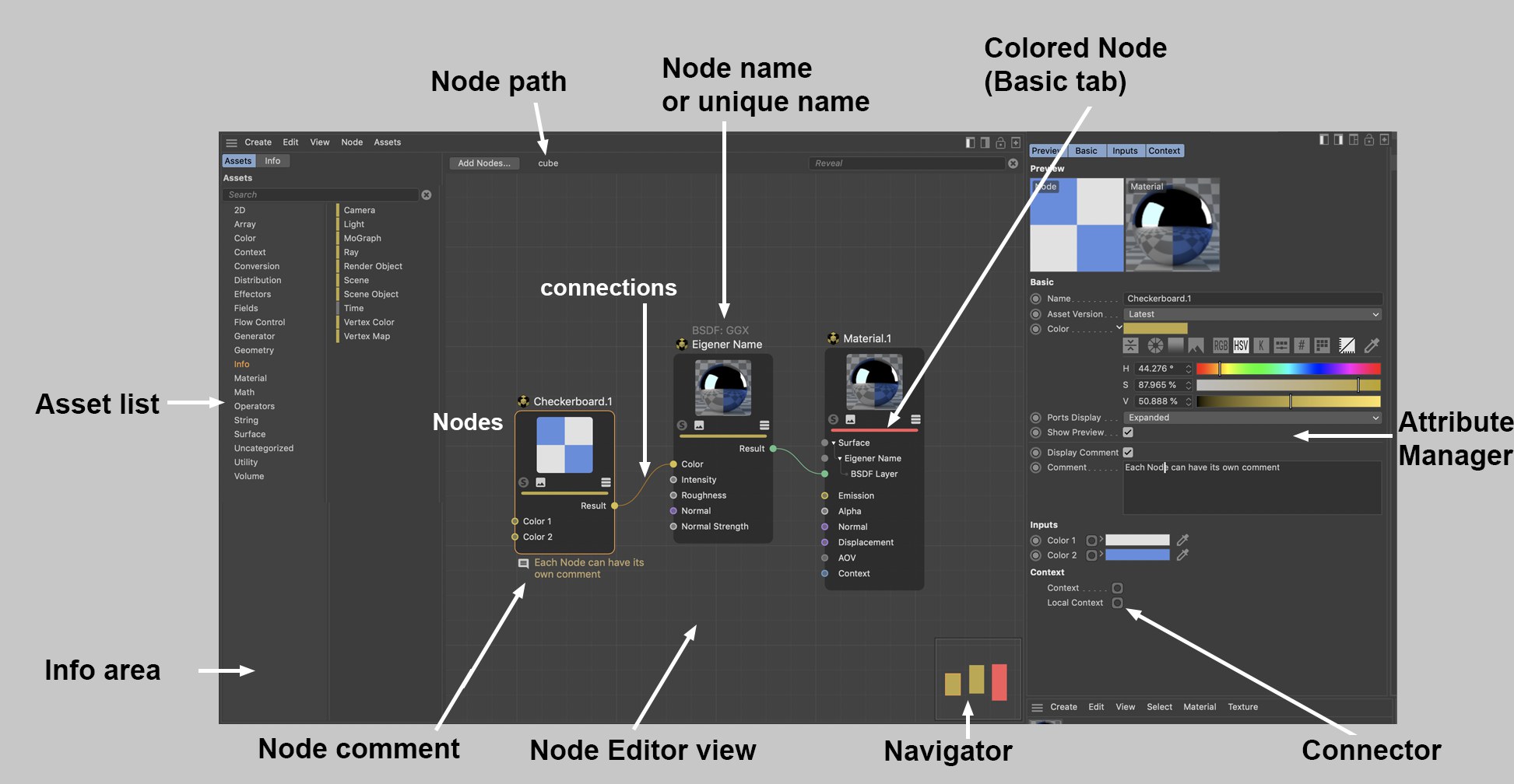
At the very top of the Node Editor you will find the following elements (from left to right):
- Add Nodes: Opens the Node Commander.
- Scene Nodes: Nodes of any type can be grouped and additional groups can be created within this group. If you open these groups, their respective hierarchies will be displayed. Clicking on a group higher up in the hierarchy will let you jump to that group. The Edit Asset mode will also be displayed here, which can be exited by closing the opened Node Editor.
- Highlight: Enter a series of characters here that affects the Nodes displayed. Nodes whose names contain this series of characters will be displayed more prominently by fading all other Nodes. This can help when looking for specific Nodes among a myriad of Nodes.

The Navigator is located at the bottom right of the Node Editor view - it’s a small depiction of the entire Node constellation and serves for better orientation and quicker navigation, especially for complex Node setups. The light gray triangle shows the visible part of the Node Editor view. You can move this section by clicking and dragging in the view.
The following Nodes have a special display:
- Colored Nodes (Basic tab) will be displayed with the identical color
- Selected Nodes are also selected
- Group Nodes will be displayed with a diagonal element
On each side of the Node you will see a dark edge (if output ports were already created). Connections/ports can be output with these areas by dropping a new connection into an empty region of the area. This makes little sense for individual Nodes but if you combine different groups with one another, you can use this method to create a port that is shown as a group port (as in the image below). This means that even in a group within a group a specific Node port at the very bottom can be connected from the outside (or as an output to the outside).
 Node ports in groups can be led
outside.
Node ports in groups can be led
outside.
When a connection is released in an empty area, a small menu will open (see image bottom left) with the following options:
- Filters with which you can filter out the elements you don’t need by entering a string of characters
- Add Input, round port: Here, the connection can be deleted without deleting the input. An input can be re-connected from the inside.
- Propagate Port, square port: If you remove the connection here, the port will also be deleted. Ports also pass on their properties to the outside, which, however, is currently barely used.
- Existing ports/inputs/outputs: If the port to be connected should be connected with an existing input or output, this can be done by making a selection from the list.
Parts of the described functionality (creating inputs) can also be done via the port context menu commands.
Note also the Input and Output Nodes, which do the same thing but can offer a better overview.
General information about Nodes
 A Node setup and display example (it’s also
possible to only display connected ports).
A Node setup and display example (it’s also
possible to only display connected ports).
The core component of the Node System is - logically - the Node. A Node has inputs into which data from other Nodes is entered, which is then processed by the Node and the result is passed to its outputs. Inputs and outputs have ports through which the connection to other Nodes can be made. Basically, an input port can only have a single connection and output can have any number of connections.
Nodes can be grabbed on the left or right edge and made wider or narrower.
A Node has an upper area and a lower area:
The Node’s name is displayed over the respective Node. If you rename the Node in the Basic tab, its new name as well as the original name will be displayed. The latter so you always know which type of Node you’re working with. This is also the name used in the Help. The name in white text can also be modified by double-clicking on it.
The upper Node area contains the Node preview - for Nodes wherever it makes sense. If the settings of the connected input Nodes change, the preview will change accordingly. You can show or hide the preview using the small icon (2nd from the left) (a command can also be used - see above).
In the Preview you will find the Solo Mode option on the left (see Solo) if the Node Preview is supported, which is, for example, not the case for Nodes in the Scene Node Editor. Next to it on the right is the Preview icon.
You can click on the third icon (only visible for Group Nodes) to display the group content in the Node View (double-clicking on the Node will do the same).
The Display Mode icon at the far right can be used to switch between port display modes, as can be done using the three port commands machen.
Below the row of icons you will see a color bar whose color is defined using the Color setting in the Basic tab. This can make it easier to find certain Nodes. By default, some Bode types are already colored but can be recolored at any time.
The lower area contains the input ports on the left with their respective names and the output ports on the right with their respective names. Ports can be hidden, and their order can be changed by moving them. Note that not all input ports will necessarily be listed in the Node itself. These can be displayed using the context menu.
Certain Nodes (such as the Layer Node, for example) even have drop-down port groups for each layer.
Depending on the data type being processed, ports will be assigned a certain color (see next data types).
Ports can be selected (using the
Inputs and outputs are colored accordingly. Fitting data types for input and outputs will be displayed using colors. The most important types are:
- Dark gray: Represents a container consisting of various data types, as would be the case when transmitting complex settings for shading for a given material or as it appears with an Op Output port.
- Light gray: Represents numeric values. This can be whole numbers (integers), percentages or a number with a comma value (float).
- Yellow: Used for color values (RGB vectors) or textures
- Blue: Used for transferring data types such as Matrix, Text, Boole, Array .
- Violet: These are ports that work with vectors, for example, in conjunction with Normals and for the displacement of a material or if an object’s position should be ascertained.
- Green: Reserved for BSDF layers for Material Nodes, which can be used to define physical shading and reflectance information.
As in XPresso, atypical input and outputs can be connected with one another. As a rule, a constructive conversion of the data types will take place. For example, a texture can also be connected to an input for a float comma value. The texture’s RGB values will then automatically be converted to brightness values. Using this method, color textures can also be used to, for example, control the Roughness of a BSDF layer. This type of conversion of data types is denoted at the receiving Node by an additional point at the respective input.
If you right-click on a Node/port, a comprehensive context menu will open, which contains commands mostly from the Node Editor menu. These are described here, except for the following:
Enter a series of characters here to filter out elements you don’t need (only commands, Nodes, etc. that contain these characters will be displayed).
Not all inputs listed in the Attribute Manager have to be displayed by the Node as a port. Sometimes only the most important are shown. Use the Add Port command to show all hidden ports. If one is selected, it will be displayed again (if All is selected, all input ports will be made visible).
This menu point is not available if all input ports are displayed.
Normally, all outputs are displayed. If not, (e.g., if Remove Unused Ports was applied) these can be displayed by selecting one of the output ports from the list.
A list will be displayed from which a Node to which you can link can be selected. If multiple output ports come into question per Node, click on the small black arrow and the output ports that can be selected will be displayed. In addition to the complete Asset list, the first entries will be existing Nodes where Nodes are listed that are contained in the current Node Editor view. There is also the Add Group Input option with which a port can be drawn from a group (see also Input and Output Group Areas).
Note that this list is created dynamically, and only fitting Nodes will be suggested.
For the current, connected input port, the "feeding" Node will be replaced by one from the list. Note that the complete Node chain will be deleted at the Node to be deleted. This only applies to the Nodes being fed: Nodes that are connected to other output ports remain unaffected.
All loaded textures are listed here. Select a texture from the list to feed it into the input port.
Selecting this option will open a context window from which you can select a bitmap or video, which will then be fed to the input port using an Image Node.
Several Nodes such as the Layer Node or the Gradient make this command available. With it you can delete elements such as Layers or Knots.
Selecting this command will hide the selected ports. This only works with ports that are not connected. The hidden port will then appear in the previously described list under Add Input (and can be made visible there).
Note also the  Show All
Ports
Show All
Ports
Most settings have a default value, which is defined when the Node is created. Using this command, modified values will be reset to their default values. This only affects Nodes that are not connected.
Calling up this command (only of use when the Node Editor view shows a group’s contents) creates a connection to the outside or to the parent hierarchy. See also Input and Output Group Areas.
A Solo functionality can be enabled for Nodes. If this Node has multiple outputs, one of them must be defined as a Solo Port, which is what this option does.
In the upper area of a Node you will find the Node’s preview. If a Node has multiple outputs, this option can be used to define which output should be displayed in the preview.
Proceed as follows to connect a Node port with another port:
Connections can also be selected, whereby you can almost always do so in conjunction with the
If ports are already connected, this command can be called up. It places a Converter Node in the connection, i.e., its input and output are already properly connected.
Deletes selected connection.
Muted connections will be displayed with a dashed line. Values will not be accepted from the previously connected Node but from the Attribute Manager instead. This lets you temporarily disable connections for test purposes, for example.

At the top right of the Node Editor you will find the following 5 icons, from left to right:
- Left column: Use this icon to display or hide the left column, which contains the Asset list as well as the Info area.
- Right column: Use this icon to display or hide the right column, which contains the Attribute Manager.
- 2-column view: Use this icon to display or hide the 2-column view. All managers (Asset lists, Info area and Attribute Manager), which would otherwise be visible in the 3-column view will all be placed at the right.
- Lock Node view: Normally, the Node view will show the Node Material currently selected in the Material Manager. If the view should not change, this option can be enabled to prevent this from happening.
- New Node Manager: This will open a new Node Editor. This can, for example, be helpful if you have a Node network made up of hundreds of Nodes and want to work in several areas simultaneously. Or you want to make the Nodes of two Node Materials visible at the same time (see also previous icon).
The Attribute Manager is available in the Node Editor in an identical form. The Attribute Manager shows the properties of selected Nodes or Node Materials. Most functions work as described under Attribute-Manager. In the following are several Node-specific descriptions (that however also work in the "old" Attribute Manager if Mode is set to Noded).
Create a Spiral Node, for example (Asset list: Shape/ Spiral):

As you can see, all input ports are also listed in the Attribute Manager. The Attribute Manager even offers more settings than the Node has input or outputs. The Attribute Manager contains all settings. The Node generally only has one selection as an input or output - Preview and Basic tab settings are not included.
Output ports are not listed here since their values result from calculations within the Node, which you can only modify indirectly by changing input values.
The most major change compared to the previous Attribute Manager are the linked fields that have been replaced by Connectors. Node inputs can either be fed with values by simply entering values for given settings or - and this is new - by connecting Node inputs with node outputs of other Nodes, i.e., make a connection (which is what Nodes are all about).
Click on the icon at the right of the setting name (the "connector") and select a Node from the Connect Node list to connect with the input that you select (you can, of course, simply connect ports in the Node Editor view). The selected Node will be created and linked:

Bitmaps can at any time be dragged from outside of Cinema 4D onto a complete parameter line *incl. parameter name, connecting icon and GUI element) to link a given setting using an Image Node.
As soon as a parameter is connected with another Node, the following applies:
- A small arrow will appear instead of the animation icon. Click on this arrow to display the settings of the docked Node.
- The setting can no longer animate these using the usual animation icon - this will then be displayed (of course you can animate the setting of the connected Node as usual). A setting cannot be controlled simultaneously by the Timeline and another Node.
The connector icon can have one of the following 3 states:

- Connected: The values flow from the linked Node to the Node input. On the right next to the Connector, the linked Node’s name will be displayed. You can click on this name to select the corresponding Node and display its settings.
- Muted: A connection to another Node exists, whose values will, however, not be assumed (instead, the values defined in the Attribute Manager will be used).
- Disconnected: The values defined in the Attribute Manager will be used.
Clicking on a connector icon will make the following commands available, from which most should already be familiar from the port context menu. The connector icon makes a similar functionality available, which makes it possible to access a port in the Node Editor per right-click.
In the following, only the Connector’s commands are described.
This command can, for example, be found in the Layer Node. The selected Node will be linked with a new layer.
Copies the connected output port to the cache.
The cached output port can then be linked with a different input port. This way, multiple inputs can be connected with the same output port.
This command connects the output port in the cache with the input on which you click. Contrary to the previously described command, a duplicate of the entire feeding Node is created.
Removes the connection from the input port.
The connection is maintained but no data will be passed. Instead, the value defined in the Attribute Manager will be used for the input. Call up the command again to allow data to be passed again.
Several Nodes such as the Layer Node or Grading Node offer this mode. Enable this mode, for example, to display the layer settings as animatable or adjustable settings. In addition, the input settings of the feeding Node can be displayed by activating one of the layers. In the following example, the inputs would be those of the Circle Node.

For the Grading Node (click on a Knot and on one of the subordinate connector icon to call up the command), the settings of all Knots will be displayed. Call up this command again to return to the previous mode.
Several Nodes such as the Distance or Value Nodes can assume the units and the parameter displays of subsequently connected Nodes for their input ports.
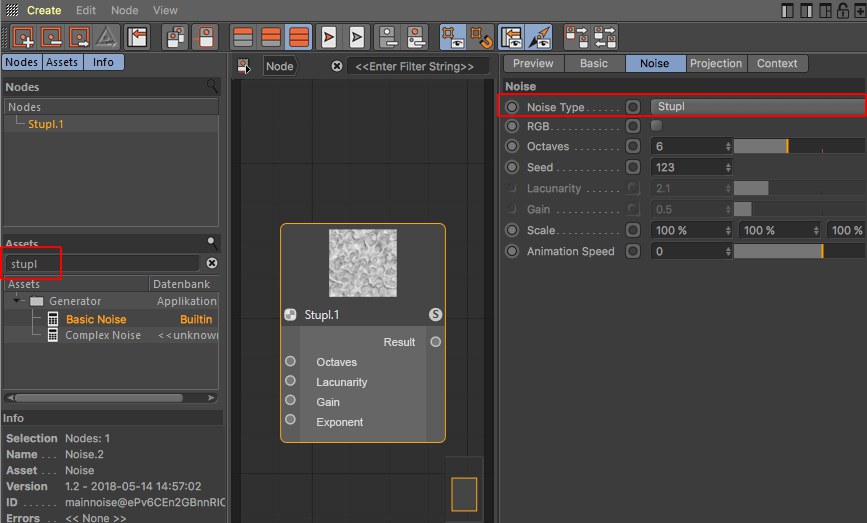
Klick on the search icon at the top right to display a text filter. Enter a series of characters to hide all nodes that do not contain these characters in their names.

In the Asset list you will find all Nodes included in Cinema 4D as well as custom Assets (the Node Commander makes the same functionality available and can be called up from
within the Node Editor using the
Example: The Color Grading Node internally contains the keywords "correction, tones, HSL, HSV", etc. If you enter these characters, this Node will be displayed. Another example would be noise names (e.g., Luka, Stupl, etc.), with which Noise Nodes can be located. A special function is also used here: if you create an Asset containing ,Stupl’, it will be set to the Noise TypeStupl. This also works, for example, with the Mix Node (type ,multiply’, for example).
For several Nodes such as the Mix Node, this can even be taken further. For example, if you filter for ,multiply background’ (several characters are combined with a logic AND) and create a Mix Node, both the Mix Mode and Use Alpha selection menus will be set accordingly.
The Node name itself will, of course, also be found (and will be given a higher priority than the keywords).
Multiple selections can be made in the Asset list (use
An Asset can be created via double-click on the filtered list. Alternatively, you can also use the cursor keys
to navigate and create the selected Asset via
Information about creating and managing Assets can be found under Assets (here, all context menu commands are described).
At the bottom left you will find the Info area in which you will find information pertaining to Nodes, connections and ports.
For Nodes:
- Selection: The number and type of selected elements
- Name: The Node name as it is defined in the Basic tab
- Asset: The non-modifiable Asset name as it is defined internally. Why do the Asset and Name infos differ? You can change the Name at any time which will differ from that in the Help. Since Cinema 4D R23, however, both names will be displayed on the Node.
- Version: When you create Assets, a version number can be defined, which is then displayed here, including date and time. This way you always know which Asset version you are currently using.
- ID: A unique ID, which has no additional informational value for you.
- Errors: Here all errors will be displayed (e.g., if an automatic conversion of a data type failed)
Additional information for connections:
- Selection: The number of selected connections
- Port Type: The data type that the port expects as input or itself puts out
- Connected Type: The data type that flows through the connection
Additional information for ports:
- Port Value: If a port has no connection, the value defined in the Attribute Manager will be displayed
Note that, depending on the Node Editor, different commands will be available. They are all described here.

The Node Commander offers functionality similar to the links in the Node Editor’s Asset
list. You simply have to press the
In addition to the functions described in the Asset list, the Node Commander offers the following functions:
- Pressing the
Esc key or clicking outside of the Commander will close the window (the order of the characters in the filter will be maintained) - Pressing the
TAB key switches from the list to the filter field - Pressing
Shift +TAB switches from filter field to list

Opens the Material Editor for the material currently displayed in the Node Editor. In principle, the Material Editor has the same settings as the Attribute Manager for a selected material.

This command selects the corresponding Node Material in the Material Manager for the active Node Editor, whose material settings will then be displayed in the Attribute Manager.

Creates an empty group for the current Node Material.

Click on the Folder icon or double-click on the Group Node to open the group.
Groups are summary, parent Nodes that contain a network of Nodes (and/ or groups as well) The ports of Nodes in these groups can also be propagated outwards in order to feed values from Nodes outside of the group or to access values of Nodes within the group.
Groups can be converted to Assets and passed on.
You can also select multiple Nodes and group them using the following command.


Input and output nodes have the same functionality as the Input and Output Group Area: they lead ports outwards so that these inputs and outputs are directly ,accessible’ in the parent group. Any number of input or output nodes can be created. The advantage compared to the Input and Output Group Area: dozens of connections don’t always offer the best overview, which can make placing input or output nodes near the connected node port difficult. You will not have extremely long connections that block your view or are difficult to navigate through.
Right-click on an input or output Node and select
Ports in the Input and Output Group Area can be dragged by their name into the node view to convert them to input or output nodes.

Multiple Node ports can be connected with the same Node input port (on the right of image abovee) - contrary to output ports where this will not work.
Multiple node ports can be connected with the same input node port; contrary to the output node where this will not work.

Groups selected Nodes (see also previous command).

Ungroups grouped Nodes and deletes the Group Node. Connections are maintained - as well as outwardly, if possible.
Tip:To unpack Assets they must be converted in groups first.
Creates new input/ output ports. This is only useful for Nodes within groups (see also Input and Output Group Area).
With this command you can create parameter input ports for all selected ports. See Input and Output Group Area for differences between input and output ports and propagated ports.
Details about Assets can be found under Assets.

Assets are most often created from Group Nodes (an example process is described here).
As soon as this command (or several - they will be processed in the order they are called up) is called up for a selected Node, a dialog window will open:

Define a name for the Asset. This Asset will appear with this name in the Asset list. This name will also appear in the Info area if you use it in the Node Editor view as an instance (i.e., you drag it from the Asset list into the Node Editor view). Even if you rename the Node, this name will remain unchanged.
Assets can have several versions (versioning). Imagine you create an Asset, build a scene with it and save the scene. You then edit the Asset (right-click on the Asset in the Asset list: Edit Asset) by, for example., changing a color or adding Nodes. If you now save the Asset (Save New Version) you can use the Version Tag to define a version (e.g., 1.1 or Version 2, etc.). The Asset will then contain both the original and the new version.
If you now load the originally saved scene or use the Asset anew, the newest Asset version will be used by default. You can, however, switch between versions in the Asset instance (i.e., the Group Node) at any time:

You can also imagine versioning as follows: Assuming you saved a primitive cube in Cinema 4D R15. A Fillet setting was added in R18. If you load the R15 scene into R18 you often had a compatibility mode that lets you load and older version. If the option is enabled, the cube is loaded without fillets, if disabled, with fillets. Sometimes the cube would be loaded without any prompt regarding its older state. If versioning were applied to primitives, you would be able to switch back-and-forth between versions.
MAXN can update the nodes it supplies in the application via the Online Updater. This is done in a manner that ensure that older scenes remain functional.
What you define here in the Version Tag will subsequently appear in the Asset instance as the Asset version name.
This is a unique ID (you don’t have to enter anything) is assigned with which an Asset can be clearly identified by the application. This ID - supplemented by a random set of characters - is then displayed in the Info area of the Node Editor when the respective Node is selected.
Assets can be saved in different databases.
Most often, the following will be offered:
- Preferences: Assets will be saved in the default directory userrepository
- Scene: An Asset copy will be copied in the scene file (this also happens if the scene is saved using the Save Project Including Assets option).
- + Databases that are linked in the Preferences menu under Files/ Paths/ Databases. Note that Assets linked as ZIP files in databases cannot be saved in these)
This menu is dynamic and will display all corresponding locations.
If you take a look at the Asset list you will see numerous Assets in the alphabetically arranged categories. You can add categories at any time (these are themselves Assets by the way).
The Asset to be saved will be placed in the selected category. If you select New Category, a new category can be created using the New Category Name option. Custom Assets can be dragged and dropped to other categories.
Clicking on OK will save the Asset and add it to the Asset list and will make it visible in the Node Commander where it can be used.

Asset Nodes, which are mostly created from groups, can be converted back to Groups using this command. The arrow icon will then be displayed again.

Opens the group.

When editing existing Assets, modifications made should be saved using this command. A dialog window will open that you should be familiar with from the Save Asset command (see above). Since the old Asset state is also saved, versioning will be implemented.

When editing existing Assets, a new Asset can be saved without the aforementioned versioning. A dialog window will open that you should be familiar with from the Save Asset command (see above).
If you open an Asset using the Edit Asset command, you will be switched to Edit Asset mode. Calling up this command will exit this mode. You may be prompted to confirm or discard the changes made to the Asset. Changes made to Assets must be confirmed (e.g., via Save New Version).


These are the usual commands with which you can delete changes made in the Attribute Manager or undo/ redo functions. Contrary to the XPresso editor, moving or expanding Nodes is not included for these functions.


Here you can copy selected Nodes to the cache (for Cut, the Nodes will also be deleted) and Pasted in the Node Editor. Existing connections between the selected nodes will also be copied.

Selected Nodes will be duplicated, (including all existing connections).
Alternatively you can Cmd/Ctrl + click on selected nodes and move them. This will duplicate them automatically.

Selected Nodes will be deleted. Pressing the


Selects or deselects all Nodes.

Selects all Nodes connected to the selected Node. This makes it easy to select a series of connected Nodes.

Here you can access specific Preferences settings for the Node Editor.

These commands can be used to show or hide the Node’s preview (in the upper area of each Node). The application’s Preferences menu has a Material tab in which a default setting defines if the preview for new Node creation should be visible or not. What good does it do to hide the preview since it actually offers valuable information. Well, for very extensive Node networks it can be very computationally intensive to update all previews when changes are made. In such cases it can be useful to hide the preview.

Hide all Ports hides the port area for all selected Nodes, The connections are maintained. This is a purely optical effect, for example, to get a better overview of your setup. Calling up the Show all Ports command will reverse the effect.
Selected ports can also be defined as hidden with the Del key. The Show all Ports command will then not make these visible again. You will have to define the respective port as being visible via the Add Input command.
The funciton of the following two commands can also simply be accessed for each Node using this icon:


Only the ports with connections will be shown for the selected Node. All others will be hidden. This can be undone using the Show all Ports command.

In the Material Node Editor, the Solo Mode works as follows (Nodes don’t necessarily have a preview; these are, for example, useless for Nodes in the Scene Node Editor):
 Different Nodes defined as Solo Nodes, rendered
texture on a cube.
Different Nodes defined as Solo Nodes, rendered
texture on a cube.
The enabled Solo Node mode omits all other Nodes. In the Node Editor view and for rendering, only the Nodes fed into the Solo Node and the Solo Node itself will be evaluated and displayed. This is, for example, very useful if your Node preview is too small because you can display or render the effect of individual Nodes at any scale.
Use this command for a selected Node (possibly with a selected output port: see also Solo port) or simply click on the Node’s S icon.
Logically, only a single Node can be a Solo Node. To exit the Solo Node function, call up the Set Solo Node / Port command or simply click again on the S icon.

The Solo mode works as follows in the Material Node Editor: Node Materials can be made up of very complex networks consisting of hundreds of Nodes. If you want to make minor changes to a material without diving too deeply into the Node Editor, one Node - a single Node per Node Material - can be defined as a Start Node. This Node’s inputs (and only this Node’s inputs) will be displayed in the Attribute Manager or the Material Editor’s Input tab when the material is selected.
If, on the other hand, you only want to display a few ports and you’re working with groups, propagate the respective ports from the group and define the Group Node as a Start Node.
Start Nodes will be marked with a green frame if unselected.
In the following example, only the Spiral Node’s Arms setting should be displayed as an externally controlled setting. Proceed as follows:
-
Place all Nodes in a group by selecting them and selecting Group Node from the context menu. Open the group
(click on the Group Node’s arrow icon).
-
Right-click on the Spiral Node’s Arms port and select Propagate Port from the context menu.
-
Exit the group by clicking on Node in the Material or Group Name
-
Select the Group Node and select Set as Start Node (Node menu)
As soon as you select the Node Material, only the Arm setting will be displayed (image bottom right).

If you now click on the Group Node to select it and select Convert to Asset , the Asset will be created.
The Clear Start Node command removes the Start Node state.
Opens the Material Editor for the material currently displayed in the Node Editor. In principle, the Material Editor has the same settings as the Attribute Manager for a selected material.
This command selects the corresponding Node Material in the Material Manager for the active Node Editor, whose material settings will then be displayed in the Attribute Manager.

Unused Nodes are Nodes without connections (groups are not included). They therefore serve no purpose and can be deleted using this command.

With this command, the selected Nodes, all ports without a connection will be hidden (these can be unhidden using the Add Input or Add Output commands).

If Nodes lie outside of the Node Editor view, these can be shown simultaneously using this command. The view will be scaled accordingly to ensure that all Nodes are displayed.

Shows all Nodes in the Node Editor view. The view will be scaled accordingly.

Selected Nodes will be displayed at the center of the view without changing the zoom factor. For multiple selections, the center of the selected Nodes will be placed at the view’s center.

All Nodes will be placed at the center of the view without changing the zoom factor.


Enlarges or reduces the Node Editor view. Using the

If you have a Node network made up of 376 Nodes, for example, you won’t see much detail in the Node Editor view. This command sets the zoom to a quite legible 100%.

Hides or shows the grid in the Node Editor view. Grid snapping works independently of this display.

Enables or disabled grid snapping. If enabled, Node edges will snap to the grid lines.

Shows or hides the Navigator.

When working with groups you often have to delve into these, i.e., the Node Editor shows the contents of a given group. Call up this command if you want to move up a level, i.e., out of this group. Alternatively, you can click on a layer to which you want to jump next to the Node path.

Selected or all Nodes will be arranged so they are visible in the current view - compact, arranged in order and positioned horizontally/ vertically:
 Before and after the Arrange
Nodes command is called up.
Before and after the Arrange
Nodes command is called up.
With this command you can create parameter input ports for all selected ports. See Input and Output Group Area for differences between input and output ports and propagated ports.
Details about Assets can be found under Assets.

Similar to Edit Asset, only that a selected asset instance must lie in the node view.
Assets are most often created from Group Nodes (an example process is described here).
As soon as this command is called up for a selected Node, a dialog window will open:
Define a name for the Asset. This Asset will appear with this name in the Asset list. This name will also appear in the Info area if you use it in the Node Editor view as an instance (i.e., you drag it from the Asset list into the Node Editor view). Even if you rename the Node, this name will remain unchanged.
Assets can have several versions (versioning). Imagine you create an Asset, build a scene with it and save the scene. You then edit the Asset by, for example., changing a color or adding Nodes. If you now save the Asset (Save New Version) you can use the Version Tag to define a version (e.g., 1.1 or Version 2, etc.). The Asset will then contain both the original and the new version.
If you now load the originally saved scene or use the Asset anew, the newest Asset version will be used by default. You can, however, switch between versions in the Asset instance (i.e., the Group Node) at any time:
You can also imagine versioning as follows: Assuming you saved a primitive cube in Cinema 4D R15. A Fillet setting was added in R18. If you load the R15 scene into R18 you often had a compatibility mode that lets you load and older version. If the option is enabled, the cube is loaded without fillets, if disabled, with fillets. Sometimes the cube would be loaded without any prompt regarding its older state. If versioning were applied to primitives, you would be able to switch back-and-forth between versions.
MAXN can update the nodes it supplies in the application via the Online Updater. This is done in a manner that ensure that older scenes remain functional.
What you define here in the Version Info will subsequently appear in the Asset instance as the Asset version name.
This is a unique ID (you don’t have to enter anything) is assigned with which an Asset can be clearly identified by the application. This ID - supplemented by a random set of characters - is then displayed in the Info area of the Node Editor when the respective Node is selected.
Assets can be saved in different databases.
Most often, the following will be offered:
- Preferences: Assets will be saved in the default directory userrepository
- Scene: An Asset copy will be copied in the scene file (this also happens if the scene is saved using the Save Project Including Assets option).
- + Databases that are linked in the Preferences menu under Files/ Paths/ Databases. Note that Assets linked as ZIP files in databases cannot be saved in these)
This menu is dynamic and will display all corresponding locations.
If you take a look at the Asset list you will see numerous Assets in the alphabetically arranged categories. You can add categories at any time (these are themselves Assets by the way).
The Asset to be saved will be placed in the selected category. Custom Assets can be dragged and dropped to other categories.
Clicking on OK will save the Asset and add it to the Asset list and will make it visible in the Node Commander where it can be used.
Asset Nodes, which are mostly created from groups, can be converted back to Groups using this command. The arrow icon will then be displayed again.
Opens the group (or double-click on the Node).
If an asset is encrypted, this command will be grayed out.
When editing existing Assets, modifications made should be saved using this command. A dialog window will open that you should be familiar with from the Save Asset command (see above). Since the old Asset state is also saved, versioning will be implemented.
When editing existing Assets, a new Asset can be saved without the aforementioned versioning. A dialog window will open that you should be familiar with from the Save Asset command (see above).
The following material was created using Nodes only. Not bitmap or texture was used!

Load the following scene:

Here you can get an idea of what is possible using Nodes. Right-click on the material and select Node Editor to see what the Node setup looks like. Note the Plaid Group Node in which additional Node networks are nested.
Special informaiton about the Scene Node Editor
Aside from the descriptions above, the Scene Node Editor has several special features:
- The Op Output connection for severyl Nodes in the Scene Node Editor is displayed in bold:

These connections are a conglomerate of different values.
Click on the small arrow at the Op Output port to open them and display the value type. To create geometrty that is visible in the scene, a Op Output port must always be connected with the Scene port.
- Nodes in the Scene Node Editor often have not preview
- Nodes in the Scene Node Editor have no Solo Mode